Reasons for phase shifting
In AC circuits, current and voltage ideally oscillate in sync at a frequency of 50/60 Hz (fundamental frequency). There is no time offset between current and voltage, resulting in a state that is referred to as being in phase. This is referred to as a phase shift of zero degrees, which is described by the phase angle φ. However, this equilibrium is influenced by certain electrical components.
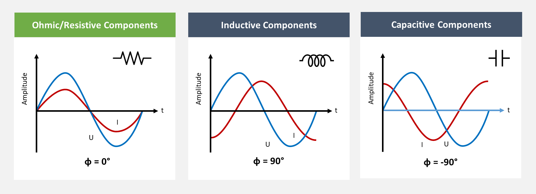
Figure 1: Influence of resistive, inductive and capacitive components
While ohmic components do not influence the phase position, inductive (coils, chokes) and capacitive (capacitors) components change this harmony.
Inductive Components
If inductive elements are connected directly (as a coil) or indirectly (e.g. in a motor, transformer) in a circuit and are subjected to periodic current changes, they generate a magnetic field. This magnetic field generates an induction voltage that reaches its maximum at the moment of the greatest current change, the zero crossing of the current. At the peaks of the current signal, the change is zero, so that no voltage is generated there. If this ratio is plotted over time, it can be seen that the voltage leads the current by a quarter of a period - the phase is shifted by +90°.
Capacitive Components
If, on the other hand, capacitive elements are introduced into the circuit directly (as a capacitor) or indirectly (e.g. intermediate circuits of rectifiers), the current flow causes charge to build up on the capacitor plates, which generates a voltage. This voltage reaches its maximum before the direction of the current changes and causes the capacitor's polarity to reverse. In the capacitor, the voltage lags the current by a quarter of a period - the phase is shifted by -90°.
Basic view on power values
In the following, the basic relationships will be considered first, focusing ideally only on the fundamental harmonic components (50/60Hz) and assuming ideal conditions, where, for example, only purely linear loads are present (current behaves linearly). The total power results from the product of current and voltage.
Active / Real / True Power P
When calculating the power at each point of the depicted current and voltage curves, it becomes apparent that in circuits with purely resistive components, the power is always positive and oscillates between zero and its maximum value in synchronization with the voltage and the current, increasing and decreasing. The power flows with the current to the consumer to produce a real effect -- hence, it is also referred to as real, true or active power. Active power is denoted by the symbol P and is measured in unit of watts (W).
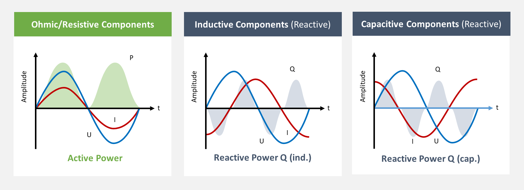
Figure 2: Active Power and Reactive Power
Reactive Power Q
In inductive and capacitive systems, due to the phase shift of the current, the situation is different. Since the power is only used for the formation of electromagnetic fields (coil and capacitor), it oscillates between positive and negative values, which cancel each other out over time. The oscillation of power during the build-up and breakdown of electrical and magnetic fields is referred to as reactive or imaginary power. Apart from conversion losses (in the form of heat), this power is not usable in any way - - no real effect can be achieved with it. To distinguish it from active power, it is denoted by the symbol Q and specified in volt-amperes reactive (var).
Apparent Power S
The exclusive use of either active or reactive power practically never occurs in practice. Therefore, the electrical network's lines must transport both active and reactive power and be designed to handle the currents that occur. The total power transported is referred to as apparent power. It is expressed in the unit volt-amperes (VA) and symbolized by the symbol S.
Fundamental Power Factor Cos φ
The effective, fundamental power factor Cos φ, utilizing the phase shift angle φ of the fundamental frequency (50/60Hz) to describe the ratio of active power to apparent power. The relationship between active, reactive, and apparent power can be visualized in a power triangle. With the help of this power triangle, the different power values can be easily converted into each other..
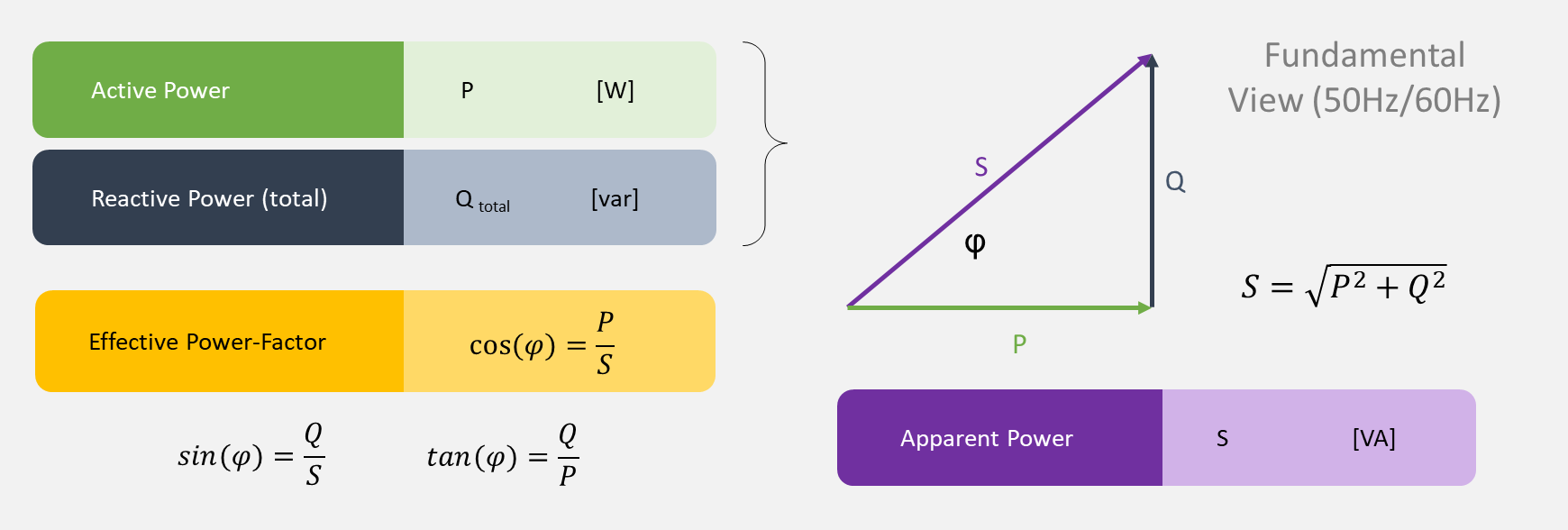
Figure 3: Power triangle and correlations from a fundamental perspective
Advanced view on power values
In reality, not only idealized sinusoidal currents and voltages occur, but these are typically distorted. The distortion is based on the nonlinear current draw of consumers in reality, such as the cyclical recharging of an intermediate circuit, which only generates a short current peak.
The distorted signals can be decomposed into various components, multiples of the fundamental frequency, with the help of the mathematical function of the Fourier Transformation (FFT, DFT). In addition to the already known fundamental components (50 Hz), higher frequency components (150 Hz, 250 Hz,...) also appear as multiples of the fundamental frequency.
The following figure demonstrates the relations:
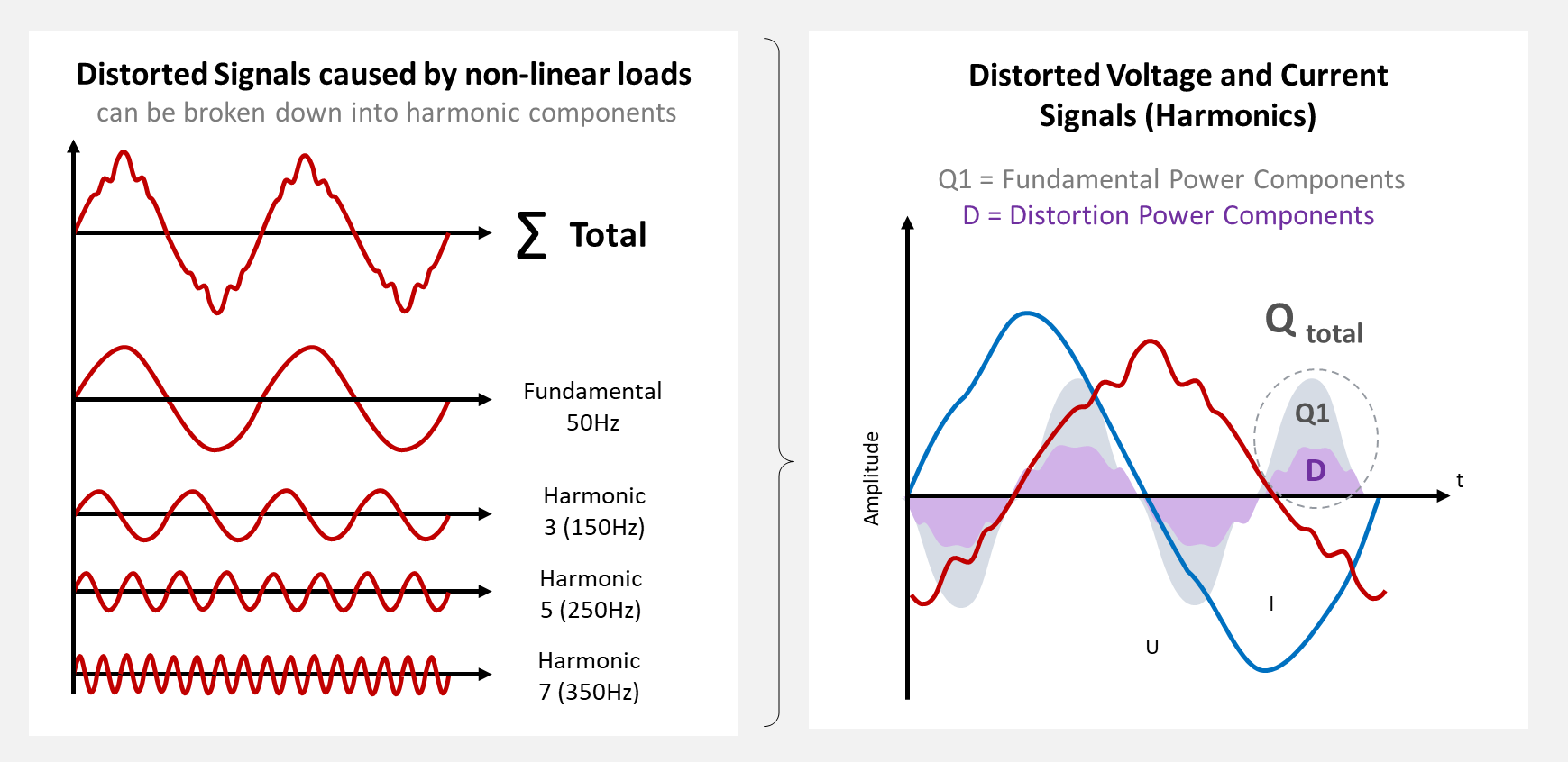
Figure 4: Distorted signals lead to distorted power values
In addition to the known fundamental component of the power, the higher-frequency components of the current and voltage signals also result in a higher-frequency component of the reactive power.
Deformation D and displacement reactive power Q1
This is referred to as distortion reactive power D, the unit is also volt-ampere-reactive (var). The fundamental component is also referred to as fundamental or displacement reactive power Q1 or Q_fundamental for easier differentiation.
The new variables can be plotted in the power triangle as the third axis and added to the figure as follows.
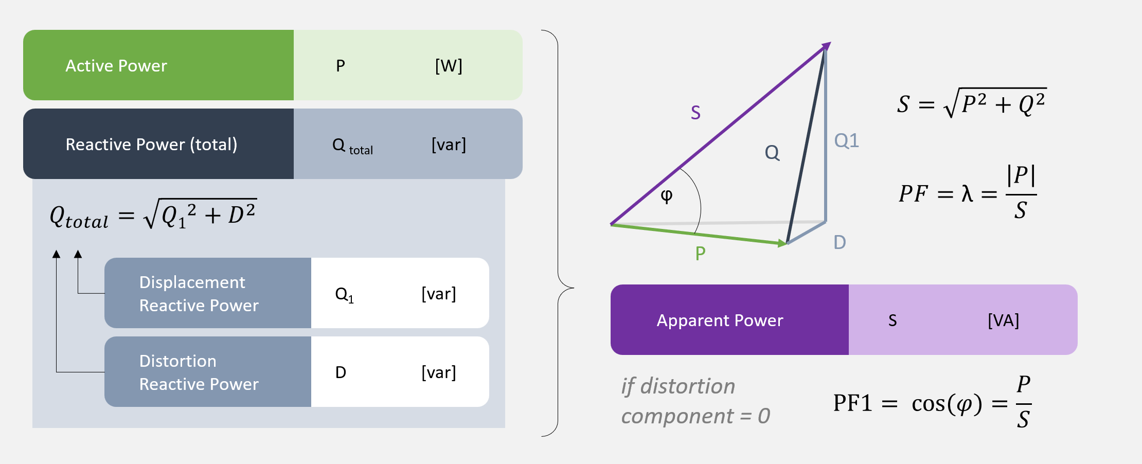
Figure 5: Deformation and displacement reactive power Q1
Power Factor λ
While it is possible to calculate the effective factor Cos φ for purely sinusoidal signals in order to draw conclusions about the phase shift angle φ, this simplification cannot be made for distorted systems. The reason for this is that each frequency component or each harmonic signal has an individual phase position - vector addition would therefore be required to calculate the resulting angle.
An additional value, the power factor λ, is therefore used to describe the ratio of active power to apparent power. It includes the higher-frequency components, but avoids specifying the phase angle φ, which could lead to incorrect assumptions.
The power factor can be divided into a fundamental component PF_1 or PF_Fundamental and a deformation component PF_D in the same way as the power. The fundamental component (50/60hz) corresponds to the already known effective factor Cos φ.
Summary
Inductivities and capacitances cause a phase shift between current and voltage. Depending on the magnitude of the phase shift, pure active power, pure reactive power or both are transmitted. In linear-systems active, reactive and apparent power can be converted into each other via the active factor Cos φ or PF_1.
Non-linear loads that do not have linear current consumption generate distorted current signals that also have higher frequency components in addition to the fundamental components. These can be broken down using the Fourier transformation. In the power calculation, the higher frequency components are referred to as deformation reactive power Q_D and the fundamental components as displacement reactive power Q1. The power factor λ is used to describe the relations in those non-linear load systems.
The compensation of reactive power, in particular to correct the power factor, is one of the fundamental tasks in the field of power quality. You can find out more about power factor correction in our article: Methods for power factor correction
- test