Active filter systems are a widely used means of addressing various phenomena of poor power quality. These mainly include effects that are caused by the specific current demand of loads (the load current of drive systems, for example) and thus determine the waveform of the load current (harmonics), the phase shift between voltage and current (power factor) and the homogeneity of the phase load (unbalance). In addition, active filter systems are increasingly focusing on the effects of the waveform and the time characteristic of the voltage, such as short voltage dips and voltage changes (flicker).
In contrast to passive filters, which work with inductors, capacitors and resistors, active filters use power electronics and control systems to react dynamically to changing situations in the supply grid. Active filters, as they are usually offered on the market, are electronic components for generating inductive or capacitive reactive power (active reactive power filters), in special cases also active power (active active power filters). Active reactive and active power filters are offered in various configurations and variants under different names such as APF (Active Power Filter), shunt APF, grid conditioner, compensation system or AHF (Active Harmonic Filter).
The basic design, functional principle, possibilities, and limits are almost identical for all manufacturers, except for a few special versions. Special designs include special variants such as active power filters with integrated active energy storage (e.g. battery packs), which are not considered further here. The focus is on active reactive power filters.
Functional principle
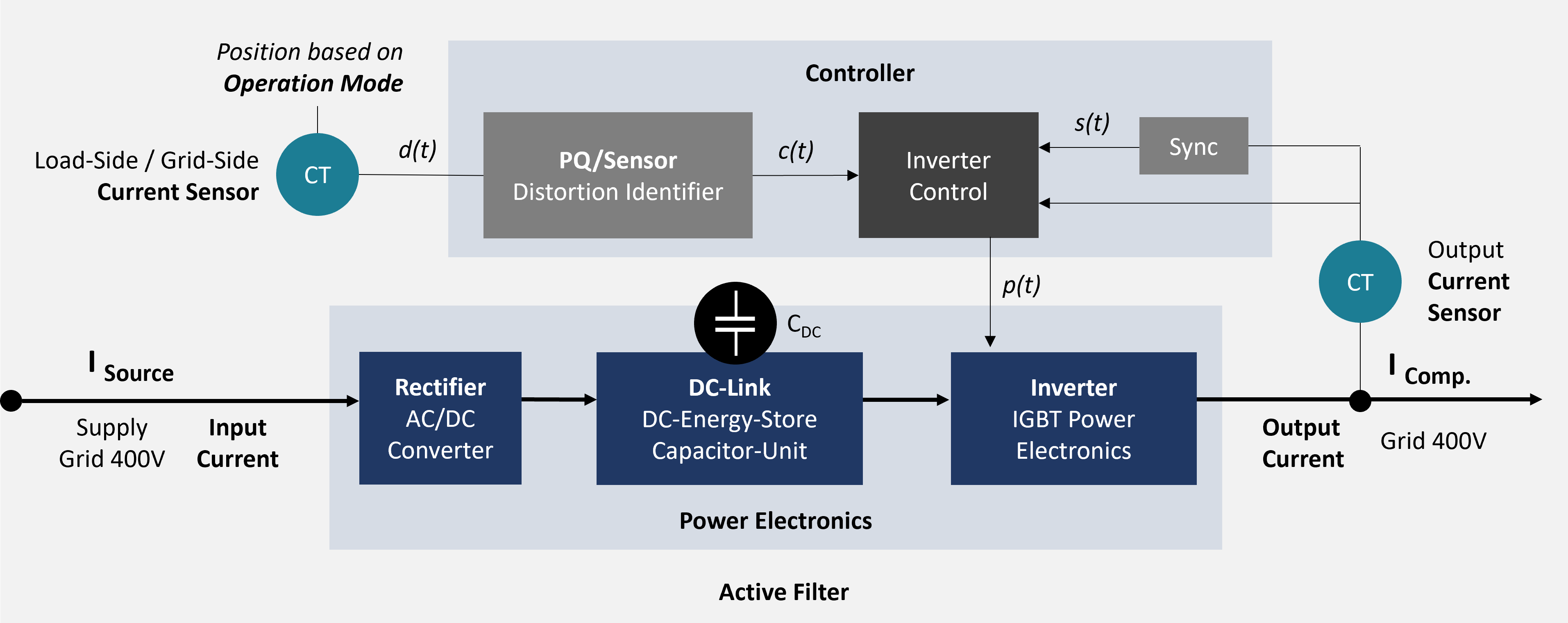
Figure 1 – Schematic diagram of an active filter
As already mentioned, active reactive power filters are controlled current sources that can generate a largely freely definable reactive currents (capacitive/inductive) based on a reference signal via control algorithms and power electronics. The reference signal required for this (the load current) is usually acquired via an external measurement transformer (CT/current transformer) - systems that do not use a dedicated external transformer but instead measure directly at the connection point of the power electronics can be commonly found on the market under the name "sensorless".
The distorted current signal of the load current d(t) is analyzed via a sensor function block (distortion identifier) and broken down into its components (e.g. FFT). From this, a corresponding compensation current signal c(t) is generated, which is ultimately used to compensate for the interference components of the detected load current. In the simplest case, this signal corresponds to the inverted (180° phase-shifted) interference signal (analogous to the function of noise-canceling headphones).
A synchronization block (sync block) ensures that the compensation currents to be fed in are synchronized with the supply grid and generates a corresponding synchronization signal s(t). The compensation and synchronization signals are combined in the inverter controller, which uses them to generate a pulse pattern/cycle p(t) for the power section of the active filter.
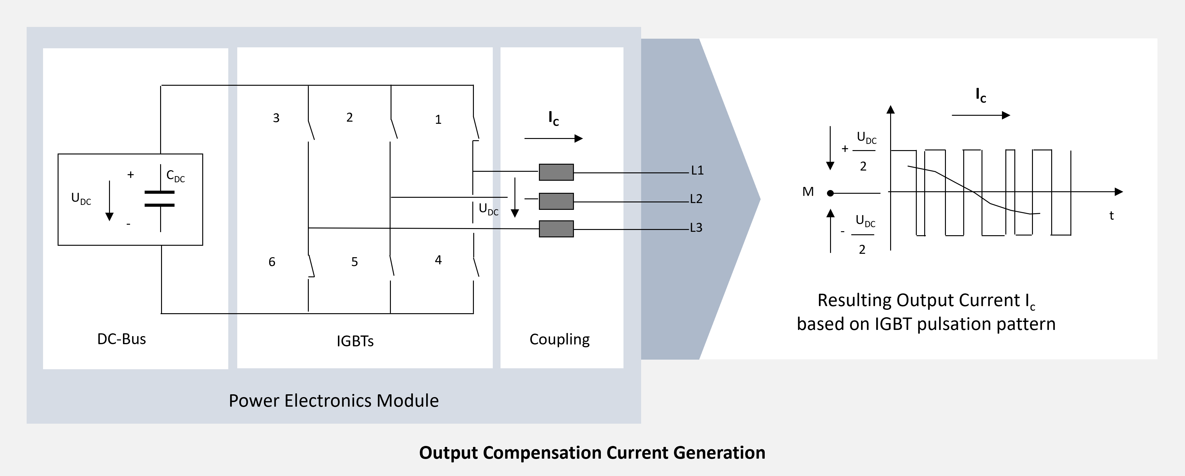
Figure 2: IGBT Power section / equivalent circuit diagram
For filters used in the low voltage range (< 1 kV), the output side (power section) of the active filter consists of a coupling inductor (choke for damping unwanted feedback), an IGBT power section (insulated gate bipolar transistor) and the capacitor unit of the DC link C_DC. For applications in the range > 1 kV (medium voltage), the coupling inductor is replaced by a coupling transformer.
The IGBTs can be regarded here as controlled switches (Fig. 2). If the IGBT switches 1 and 6 are closed, the voltage at the DC link capacitor U_DC is between L1 and L3. Any reference voltage can be set by clocking the IGBTs accordingly based on the pulse pattern generated (by the inverter controller). By varying the pulse pattern over time, almost any current signal can be generated, limited by the clock frequency (e.g. 20 kHz) of the controller, the selected control method and the hardware components used. The energy required for this is provided via a direct current intermediate circuit (DC link). A capacitor module, which is continuously charged from the supply grid via a rectifier, usually serves as a storage medium. In addition to the storage role, this capacitor module also smoothes the voltage rectified by the input circuit of the filter and ensures a constant DC bus voltage (typically approx. 800 V).
Since there is usually no additional direct current source (e.g., a battery pack of a PV system) is attached to the DC bus, this also results in the previously mentioned limitation for the current signal generation I_Comp as a controlled reactive current source – because the capacitor units used here can logically only provide reactive power and no active power. The current flow I_Comp arises when there is a potential difference between the voltage at the grid connection point and the generated DC source voltage U_DC, which leads to a voltage drop at the coupling inductance. The compensation current can then flow into the grid to compensate for the detected distortion currents.
The power electronics are usually designed in a compact modular way and integrated together with the control hardware, the electronic elements for mains connection and the internal power supply in standard industrial enclosures (e.g. Rittal). The cabinet design with modular power modules allows the active filter system to be scaled according to the performance requirements of the application by selectively expanding the number of modules. In addition to the cabinet version, small wall mount modules are also available for special applications, which integrate the individual components in a slim housing - these systems are generally not scalable in terms of their power.
The power is usually specified as the maximum deliverable reactive current (e.g. 60A per power module). Depending on the prevailing mains voltage, the system output (reactive power supply) can then be calculated, e.g. 400V x √3 x 60A x 5 modules ⇒ approx. 200 kVar
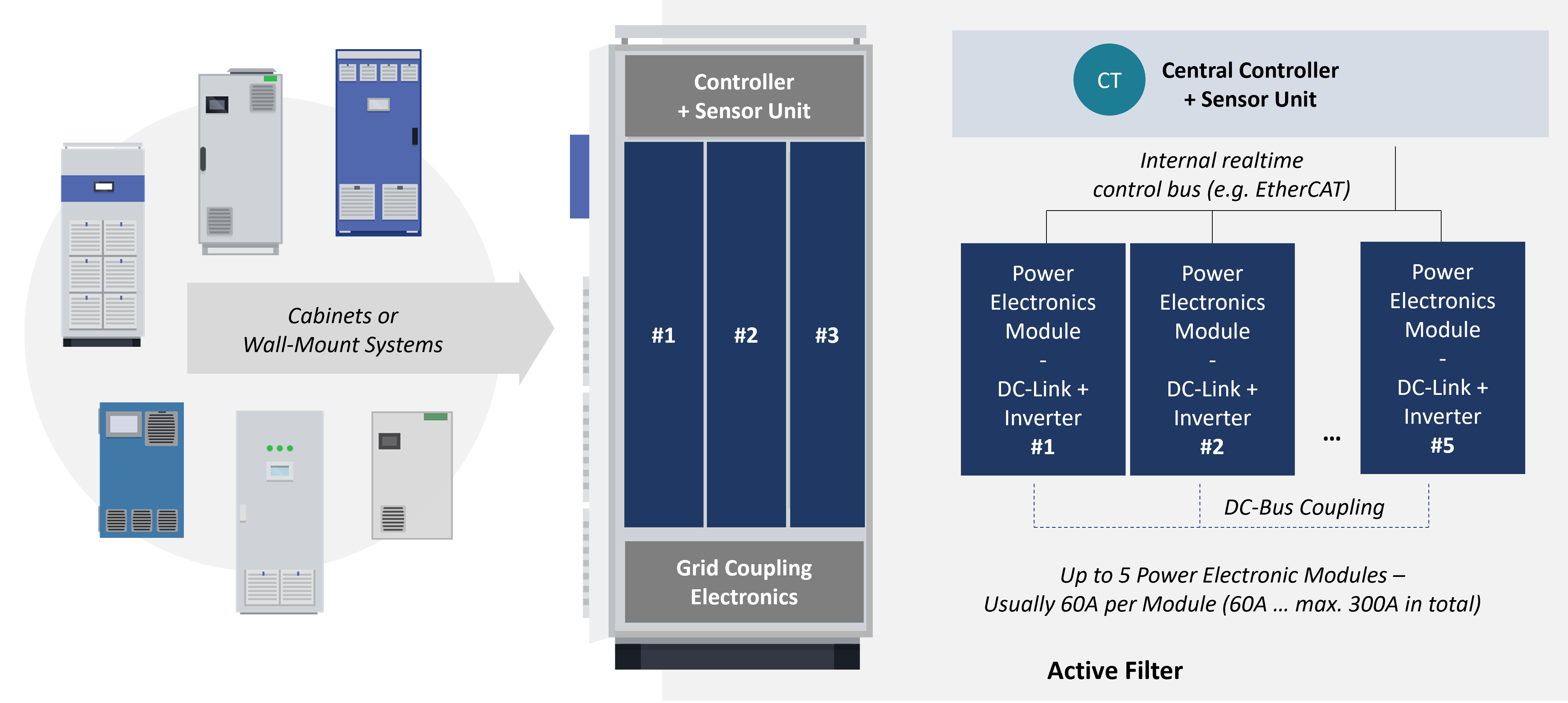
Figure 3: Assembly and Layout
Summary
Active filters are controlled reactive current sources that make an important contribution to the mitigation and stabilization of industrial distribution grids. Depending on the disturbance levels detected and different control algorithms, active filters generate reactive currents that are fed into the grid via power electronics to compensate for the disturbance phenomena. The addressable disturbance phenomena depend on the hardware and the control algorithms on the one hand, but also on the selected connection configuration on the other. You can find out more about connection configuration in our article "Connection configurations of active filters".
As active filters are active grid participants, continuous monitoring and monitoring of their operational efficiency is of crucial significance. Failures and malfunctions or premature wear can increase the risk of failure and compromise your process. In the worst case, incorrectly parameterized active filters can act as interferers and threaten your grid stability (e.g. by creating resonance points). Our experts will be happy to advise you on the selection, parameterization, and monitoring of your active filter systems vendor agnostic. Our real-time grid condition management solution GRIDNOW supports a large number of active filters available on the market and, in addition to continuous monitoring, also offers the option of automated remote parameterization. Please do not hesitate to contact us for further information.