Regarding the mains connection of active filter systems, there are two basic configurations that can be distinguished: the parallel/shunt and series connection. There are also several hybrid or combined configurations possible.
Parallel configuration
In the parallel connection also known as shunt configuration, the active filter is connected in parallel to the load as a reactive current source. This configuration is also the simplest and most frequently used. In this setup, the components of reactive displacement power and reactive distortion power generated during load tapping I_Load are directly reduced by the compensation current I_Comp injected by the active filter in parallel with the source mains current I_Source.
The following figure illustrates this basic connection diagram:
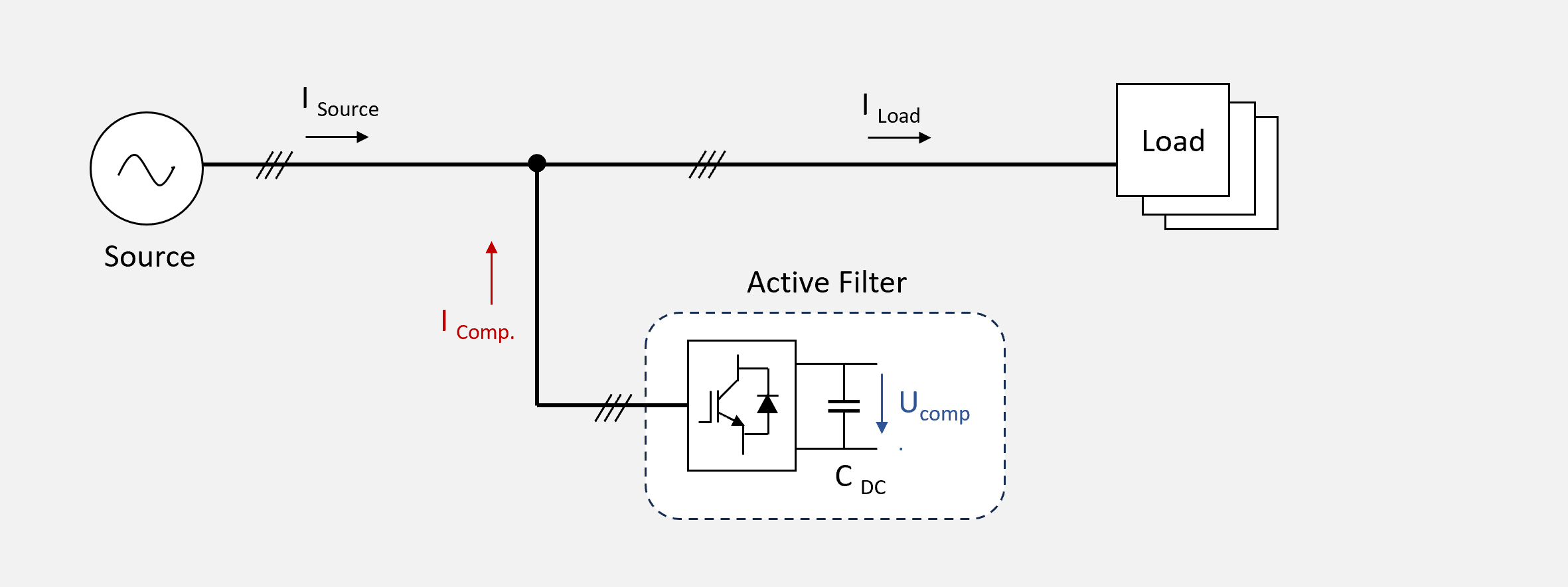 Figure 1 – Default configuration of the parallel configuration with directly connected active filter
In parallel configuration, active filters are particularly suitable for correcting the power factor and reducing harmonics. They can also be used to reduce unbalanced loads (load balancing mode). To a limited extent, this configuration can also be used to reduce flicker caused by rapid voltage changes. As the active filter uses a capacitor in the DC link C_DC as its energy source, it can only feed inductive or capacitive currents into the supply grid without an additional supply of active power (see article on the operating principle of active filters) and can therefore only indirectly influence voltage change effects (such as flicker).
Series configuration
In the series configuration, the filter is connected in series with the load via a coupling transformer. The reactive currents I_Comp generated by the active filter based on the measured load current are converted to an active voltage by the reactance of the coupling transformer - active voltage = reactive current * reactance (vector summation of complex numbers). The following figure shows this connection scheme:
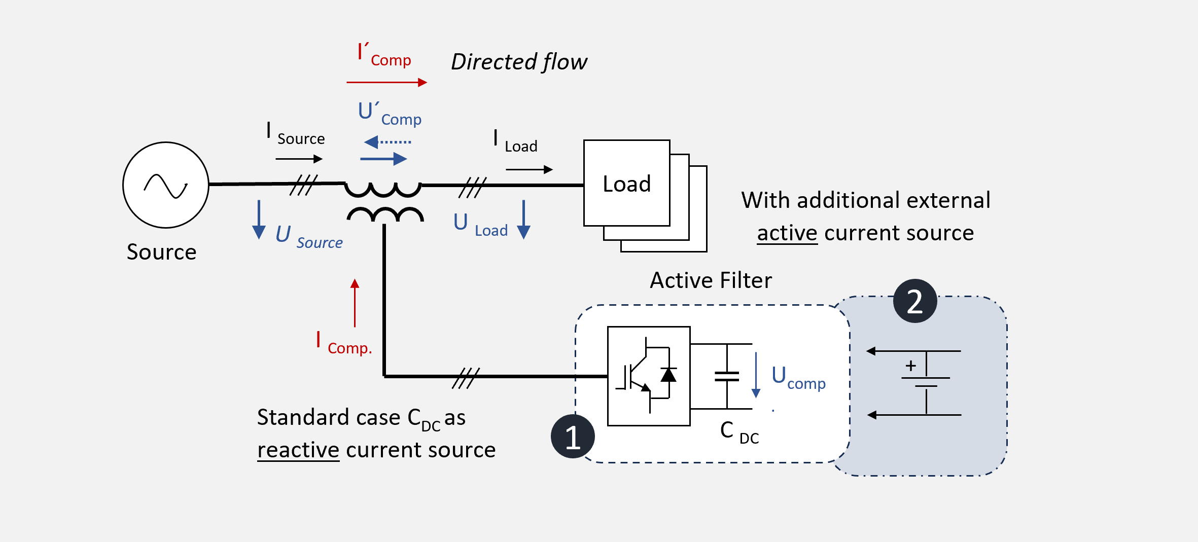 Figure 2 - Connection scheme for the series configuration
As shown in the series configuration figure, the active filter without an additional active current source is primarily used to compensate for slow and fast voltage changes and thus also for flicker. In contrast to the parallel connection, this is achieved without influencing the power factor. In addition, overvoltages and undervoltages can be corrected by selectively raising and lowering U'_Comp by providing capacitive or inductive reactive current I_Comp.
If an additional external active current source is installed, the active filter is also able to compensate for voltage dips up to complete voltage failure within certain limits. The effective compensation current on the mains side is directed and can be controlled via the compensation voltage U`_Comp.
It is important to note that with this arrangement, the impedance of the supply grid is increased by the in-series connected coupling transformer, which simultaneously reduces the short-circuit power. The reduction of the short-circuit power must be taken into account during planning.
Hybrid Configurations
In addition to the two classic connection types, many hybrid configurations can be found in the field. Variants with coupling or step-up transformers as well as various combinations to fulfil certain existing grid constraints.
One particular variant is highlighted in the following figure:
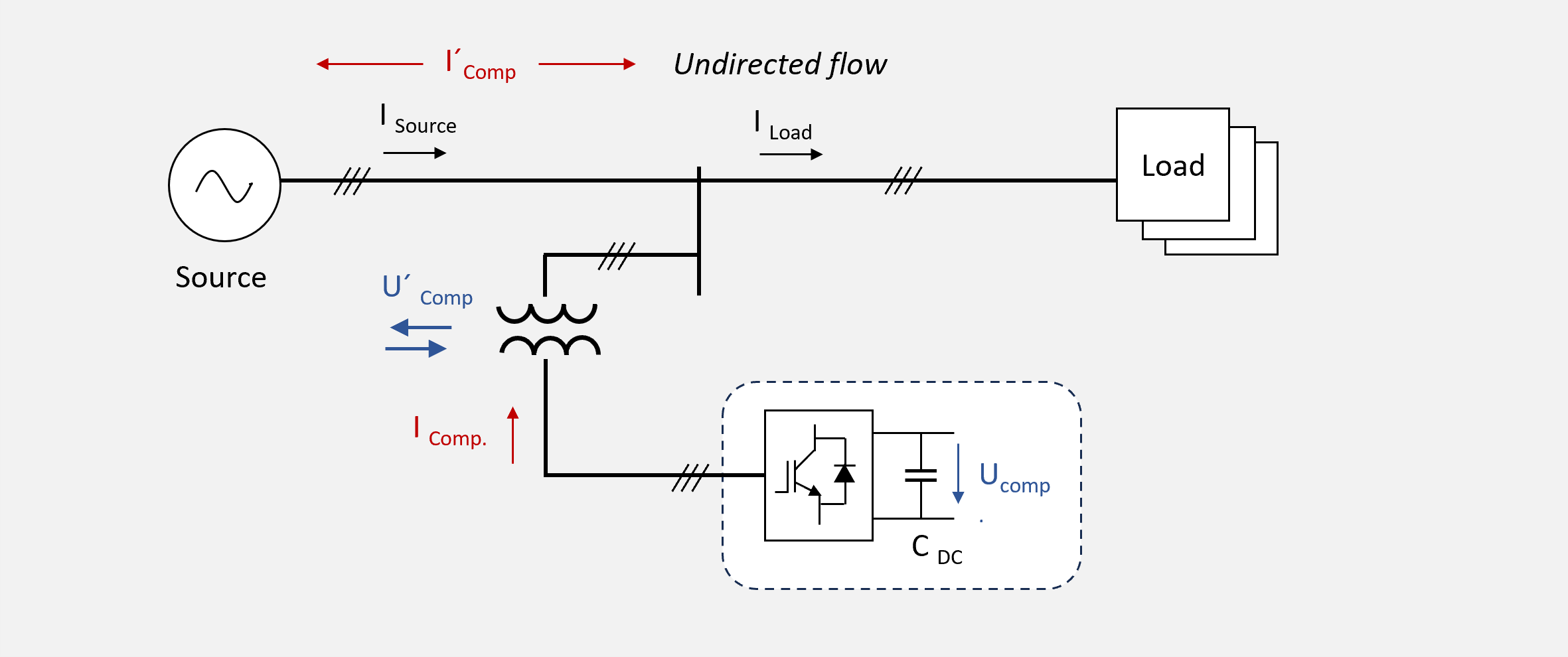 Figure 3 – Indirect parallel configuration with coupling transformer
This configuration, in which the active filter is indirectly connected in parallel to the supply grid via a coupling transformer, solves the problem of the negative influence on the short-circuit power of the supply grid in particular. The impedance of the coupling transformer has no influence on the overall impedance, but can still be used to generate U`_Comp to compensate for voltage phenomena (short interruptions, flicker, etc.).
However, it should be noted in this configuration that the generated indirect compensation current I`_comp is no longer directed and may not be able to contribute to the compensation of I_Load as it can flow directly to the source under certain conditions. This is the case, for example, if the voltage level of U_Source falls below the voltage level of U'_comp. In addition to the connection point of the power section of the active filter, the connection point of the measuring point, which determines the operating mode, is also of particular relevance. Read more about this in our article on the operating mode of active filters.