Besides the grid connection point (see article: Connection Configurations), the position of the current transformer (CT) for capturing the reference value of the active filter is a crucial aspect that can significantly influence the behavior of the active filter. Two fundamental variants can be distinguished here. Based on the position of the current transformer, a distinction is made between Open-Loop operation (load-side connection) and Closed-Loop operation (network-side connection).
Open-Loop Mode
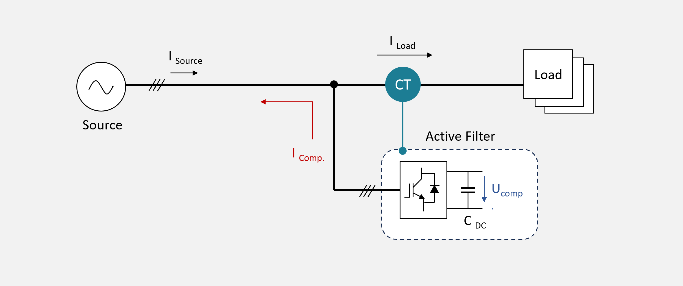 Figure 1 – Open-Loop Operation Mode
In the Open-Loop configuration, the reference value is determined behind the filter's connection point, between the filter and the load. It is called the Open-Loop Operation Mode, as the filter only sees the load current and not the compensation result from the compensation current and load current. This mode is mainly used for individual specific consumers with high grid interactions (e.g., high harmonic currents). It is the simplest and most robust form of control, as the filter only considers the actual load current as a reference value to generate a corresponding inverted compensation current.
Depending on the design, control method, and control speed, active filters in this configuration can also act as disturbers in the network, as they do not consider the actual compensation result and can thus cause instabilities. In larger systems with a variety of disturbance sources, high costs due to the high need for filters can quickly arise due to the limited focus on individual consumers.
Closed Loop Mode
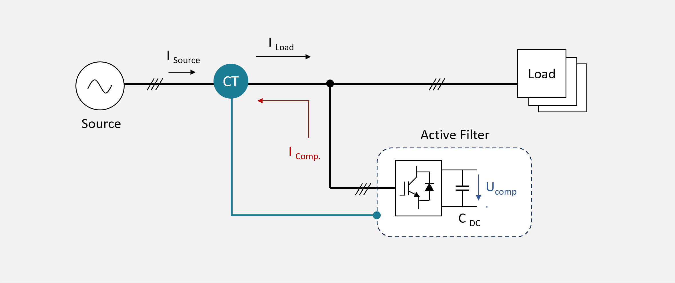 Figure 2 – Closed Loop Operation Mode
In this configuration, the required reference value is determined before the connection point of the active filter, between the filter and the source, e.g., on the low-voltage side at the busbar of the transformer station. Thus, the active filter has access to the sum of the compensation and load current. Since the filter operates based on the overall result (load + compensation) in this configuration, this variant is called the Closed-Loop-Operation Mode. By closing the control loop, the active filter can work based on its actual compensation result and take into account and correct deviations in the control result.
In principle, the Closed Loop Operation Mode is preferable to the Open Loop Operation Mode, as it can automatically compensate for naturally occurring error components (e.g., measurement errors, synchronization errors, etc.) within the control cycle. Nevertheless, this operation mode can become problematic, especially in low-load scenarios where only minimal load current flows. In these situations, it may happen that the active filter can no longer distinguish between load, compensation, and fundamental current at its current transformer. The base noise of the grid can lead to unintended excitation and oscillation of the active filter. Particularly, the parallel operation of several active filters on a supply grid section or mesh is often problematic in this context.
Since active filters are active supply grid participants (see article: Fundamentals of Active Filters) that generate highly dynamic reactive currents and feed them into the network, holistic monitoring and management are urgently required. Each filter influences the network characteristics and can contribute to both an improvement and destabilization of the power supply network (e.g., interactions, resonant circuits).