The compensation of reactive power is one of the fundamental tasks in the field of power quality. Depending on the environment, area of application and focus, different solutions are available that are based on an identical operating principle. The reasons why, the relationships, the fundamentals and some explicit solution approaches (passive filters, SVC, active filters, SVG and STATCOM) are described in detail below.
Fundamentals
As already shown in the article related to power fundamentals, the power factor λ / PF describes the ratio of active power P to apparent power S. The relationships are illustrated in the following figure:
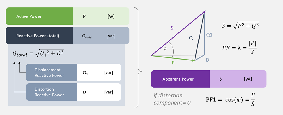 Figure 1 - Relationship between power and power factor
If the distortion component D, which reflects all frequency components greater than the fundamental frequency, is ignored, the relationship can be described by the so-called effective factor cosφ. The angle φ corresponds to the phase shift or time delay between voltage V(t) and current C(t). If the angle is between 0° and 90°, this is called inductive reactive power, where the current lags behind the voltage - this is also called lagging power factor. If the angle is between 0° and -90°, this is called capacitive reactive power, where the current leads the voltage - often called leading power factor (see Figure 2).
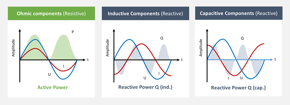 Figure 2 – Inductive (lagging PF) and Capacitive (leading PF) Reactive Power
The magnitude of the effective factor is defined as the displacement factor, which is why the resulting reactive power is also referred to as displacement reactive power Q1 (the index 1 indicates that we are talking about the fundamental component). This simplification is no longer valid when considering the distortion components D (components > fundamental Frequency) that typically occur in power systems due to the non-uniform phase shift angles of the individual harmonic components.
The effective factor Cos φ therefore always describes the displacement component in relation to the fundamental component (50/60 Hz) and is often also referred to as the fundamental factor PF_1 or PF_fundamental.
Causes of the phase shift
With purely resistive loads, the voltage and current are in phase. The cos φ is therefore 1, which means that all the energy supplied by the source is fully converted by the load. A correction is not required in this case.
However, supply networks usually also contain non-resistive components, such as inductances (transformers, chokes, etc.) and capacitances (capacitors). An example of this is the directly connected motor (asynchronous motor), which requires inductive reactive power from the supply network to generate its magnetic field. This magnetic field is first built up in the motor and then dissipated again and returned to the source when the voltage direction (AC mains) changes. This process is repeated periodically. An inductive reactive power (Q_Load) is created, which generates a rotating field in the three-phase mains at the asynchronous motor, which rotates with the mains frequency. The reactive power required for this oscillates periodically between the load and the source.
These phase-shifted oscillating components put stress on lines and infrastructure elements (fuses, switches, etc.) without any useful energetic value. In many examples, reactive power is also referred to as "foam" in the grid (cf. foam in a beer glass or water rapids, ...). Energy suppliers limit the amount of foam in their supply contracts and specify a corresponding window for the allowed power factor (e.g. 0.95 capacitive to 0.90 inductive) - exceeding or falling below the guaranteed window is usually subjected to penalties.
Power factor correction
The objective of reactive power compensation is to minimalize this angular displacement and prevent the spread of reactive power via the infrastructure or towards the energy supplier. For the correction, the opposite form of reactive power is always required, e.g. capacitive reactive power to compensate for inductive reactive power and vice versa. The following illustration shows compensation in the case of a highly inductive load:
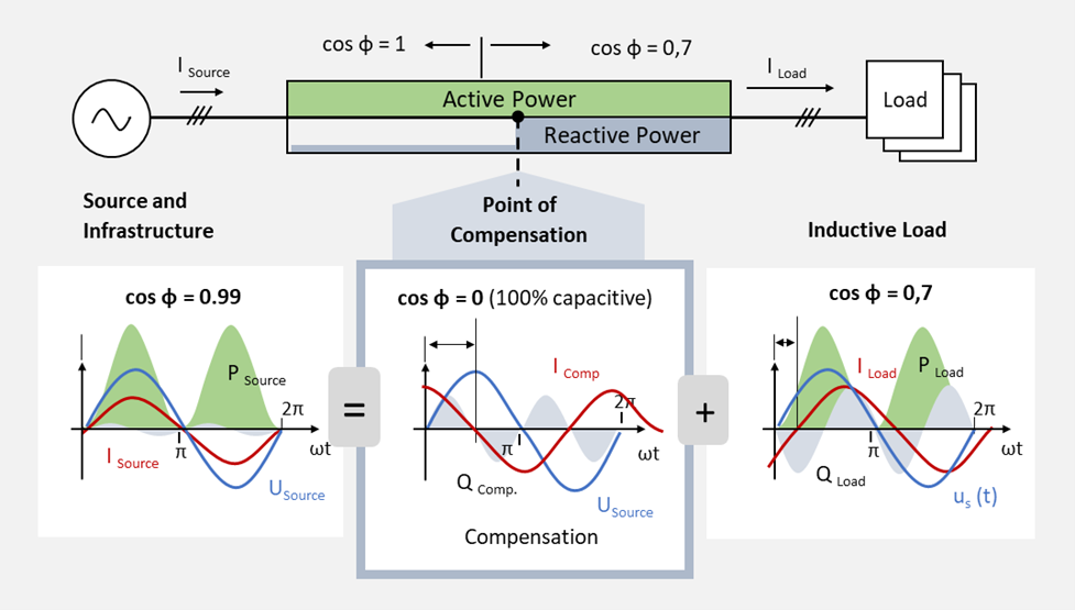 Figure 3 – Principle of power factor correction
The required capacitive or inductive reactive power can be provided via various passive or active reactive power sources, which deliver the reactive power components required by the load at a given point. The cosφ of 0.7 (inductive) caused by the load is eliminated by the capacitive compensation power in this case - the foam is therefore already eliminated at the source and thus relieves the rest of the infrastructure.
The reactive power sources required for this can be differentiated according to various criteria and areas of application. Each type of provision has different advantages, disadvantages and areas of application. For details, we also recommend reading the relevant in depth articles.
Passive Compensation
In the past, mainly passive compensation systems were used in which tailored filter stages, consisting of a combination of selected capacitors and inductors, are switched on or off via a switch (contactor) or thyristor. Control takes place via a power factor controller (PFC), which statically switches on the required compensation stages based on the measured currents and voltages.
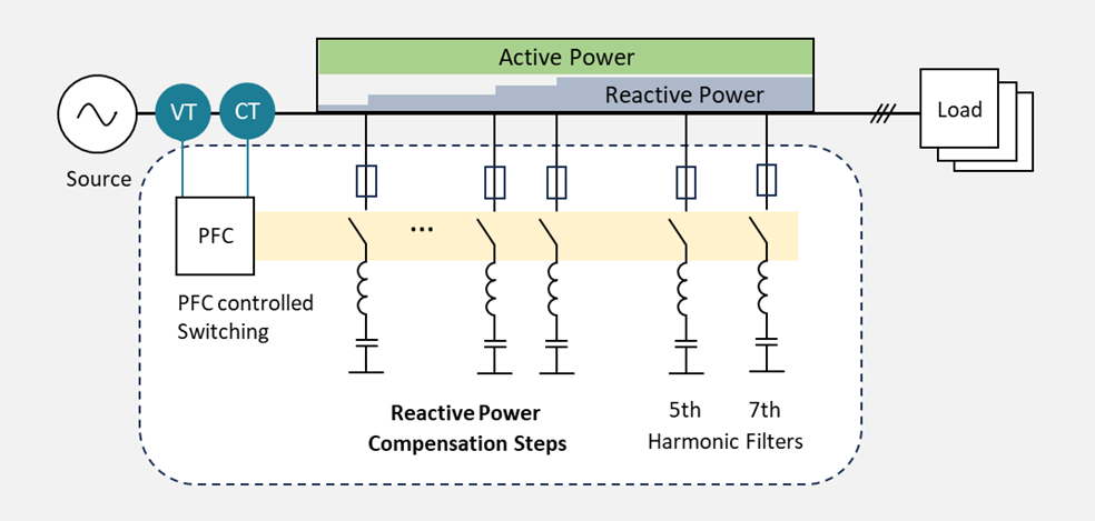 Figure 4 – Passive compensation with fixed stages
The focus of these systems lies in the staged provision of capacitive reactive power to compensate for highly inductive grids and for the systematic damping of specific harmonics. A similar design for providing inductive reactive power in the form of switchable inductance stages is not practical due to the lower fundamental impedance of the inductors compared to capacitors. This would lead to massive losses which is not desired.
Degree of Detuning
The "Degree of Detuning" is a concept distinct from the commonly installed chokes in passive compensation systems designed for the compensation of inductive reactive power. These chokes are primarily installed to protect capacitors and to prevent the creation of additional resonance points, which can be caused by the high leakage currents flowing through the capacitors. The term refers to the specific degree to which passive compensation systems are detuned, such as a 15% detuning, to mitigate these issues effectively.
SVC – Static Var Compensation
Static Var Compensation (SVC) is an advanced form of static compensation that improves upon traditional passive compensation methods. While the fundamental principle of SVC is similar to that of the passive compensation, SVC systems incorporate a dynamic component that allows for flexible and nearly continuous adjustment. This dynamic capability is achieved through the use of thyristor sets instead of mechanical switches (contactors) to connect capacitor and inductance stages. This enables SVC systems to dynamically adjust to varying demands for reactive power compensation, providing a more responsive solution to manage power quality in electrical networks.
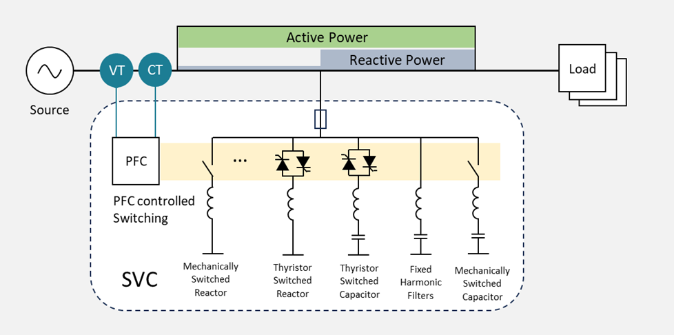 Figure 5 – Thyristor controlled Static Var Compensation
The phase control technique implemented through a set of thyristors selectively switches capacitors or inductors into the network, thereby allowing for a freely adjustable degree of compensation. Due to its simple and robust construction, such systems are particularly used in harsh environments, such as heavy industry. Thyristors, inductors, and capacitors are available for various voltage levels, making it possible, for example, to directly compensate induction furnaces at medium voltage levels. However, it is also noted for these systems that inductive power can only be provided to a limited extent and with high losses.
This means that while these systems offer a versatile and effective solution for reactive power compensation, especially where environmental conditions are challenging, there are limitations regarding the provision of inductive power. The efficiency of providing inductive power is constrained by the extent of losses incurred during operation, highlighting the importance of considering these factors when designing and implementing compensation solutions.
Dynamic environments require dynamic solutions
The limitation to compensate only inductive reactive power components and the increasing use of controlled drive systems, which exhibit significant capacitive characteristics during partial load and no-load operation, make the use of passive, static filters insufficient in many cases. Industrial power systems, in particular, experience significant fluctuations in power factor, oscillating between highly inductive and highly capacitive load behavior.
Active electronic solutions, called PQ (Power Quality) Actors, dynamically manage these fluctuations by providing both capacitive and inductive reactive power as needed. Unlike fixed capacitors and inductors that are statically switched via mechanical switches or thyristors, power electronics (such as IGBT or MOSFET power modules) are used to generate the required reactive power. In this context, such systems are often referred to as voltage source converters (VSCs), which use a controllable voltage source to provide reactive power. In contrast, thyristor-based systems are known as current source converters (CSCs), which use a current source to supply power.
This dynamic approach to reactive power compensation is essential to adapt to the rapidly changing demands of modern electrical networks, ensuring stability and maintaining power quality. By using VSC technology, networks gain the flexibility to instantly adapt to changing power quality requirements, improving overall efficiency and reliability.
APF – Active Power Filter
The active filter, extensively discussed in the article on its operating principle, is the most well-known and versatile representative of VSC-based PQ actors. Utilizing the energy stored in the DC link and an IGBT inverter, the active filter can generate nearly any voltage waveform (shape, frequency, amplitude, phase angle). Typically, capacitors are used as energy storage, which means the application scope of the filter is primarily limited to compensating for reactive power components (refer to the operating principle of Active Filters). As a universal tool, it is employed not only for reactive power compensation but also significantly for the compensation of harmonics and for load balancing. Its expanded applications, depending on the circuit and configuration, increasingly include areas such as flicker compensation and even the compensation of short-term voltage dips.
In reactive power compensation for PFC, the active filter is typically connected in parallel with the supply network and acts as a controllable source of inductive or capacitive reactive power for downstream loads. This configuration allows it to dynamically adjust to the changing demands of the network, providing a tailored response to improve power quality and network efficiency.
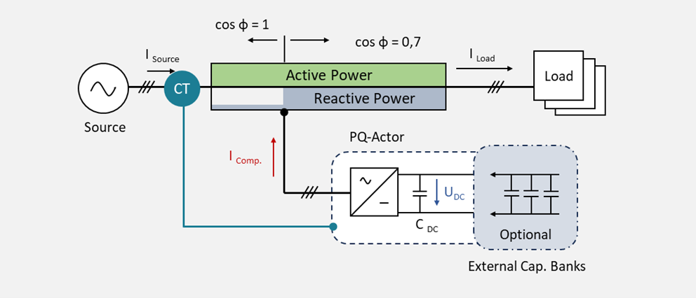 Figure 6 – Active Filter based Power Factor Correction
The advantage of using power electronics is that it is possible to switch between inductive and capacitive power within half a cycle, limited only by the response times of the controller. Based on the measured load current, the VSC-based drive can thus provide the reactive power components required by the grid almost simultaneously with the demand. This relieves the infrastructure from the filter back to the source according to its capacity.
SVG – Static Var Generator
The Static Var Generator (SVG) is a variant of the VSC-based PQ actuator specifically designed to improve the power factor. Its construction, setup, and operation are similar to those of the active filter described earlier. However, by focusing on processing the fundamental frequencies (50/60Hz), extensive data analysis (e.g., FFT - Fast Fourier Transform) is not required. This simplification of control facilitates shorter reaction times.
Static Synchronous Compensator - STATCOM
The Static Synchronous Compensator, or STATCOM, is another variant of the PQ actuator. It utilizes a specific connection and control scheme to contribute to voltage regulation and thus to the stabilization of the power network, mainly through the dynamic absorption and provision of reactive power.
The fundamental principle of the STATCOM is comparable to that of the SVG, as it also focuses on the fundamental frequency components of 50/60 Hz. To increase efficiency, the DC link of the system is designed to be significantly larger and partly open to the outside, allowing for the connection of external energy storage devices, such as supercapacitors.
This design enhances the STATCOM's ability to respond to fluctuations in the power network by quickly adjusting the amount of reactive power supplied or absorbed. The option to integrate external energy storage further improves its performance, enabling the STATCOM to maintain voltage stability more effectively over a wider range of conditions and to contribute to the overall reliability and efficiency of the power distribution system.
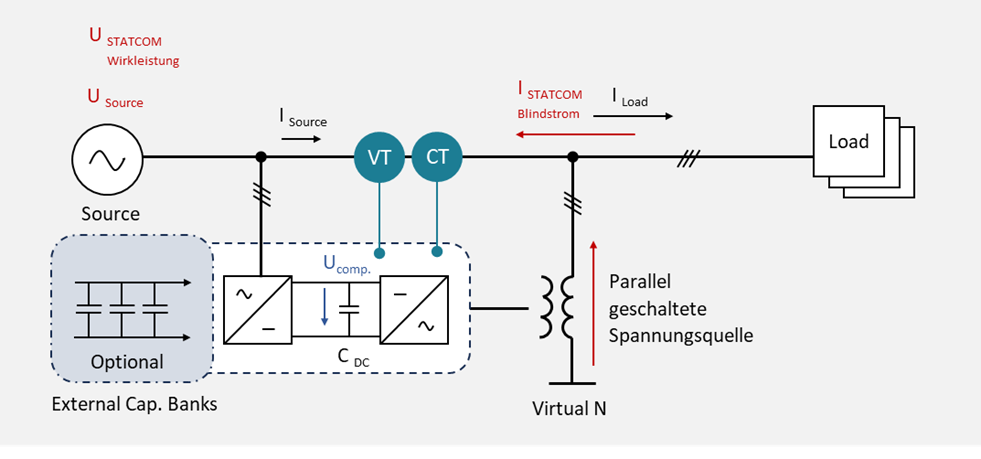
Abbildung 7 – STATCOM
Summary
Reactive power compensation plays a critical role in improving the power factor, thereby increasing the efficiency and stability of power systems. Passive compensation with fixed steps and filters is a traditional method that reaches its limits in dynamic networks with fluctuating loads. Modern active compensation methods such as APF (Active Power Filters) and SVG (Static Var Generators) offer flexible and fast adaptation to changing load conditions, thus improving the grid quality more efficiently.
The demand for dynamic and efficient reactive power compensation is expected to grow with the increasing complexity and dynamism of power grids, as well as with the growing number of controlled drive systems, regenerative systems (e.g. active front ends) and especially with the integration of renewable energy sources (e.g. photovoltaic systems).
Comprehensive management and control of distributed systems with goal-oriented, overarching system control will become increasingly important. This approach will ensure that power grids can adapt to the evolving needs of modern energy systems and maintain stability and efficiency in the face of diverse and dynamic energy generation and consumption patterns.